Product Description
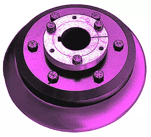
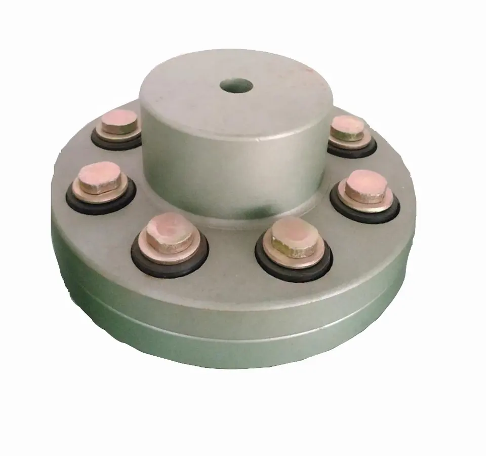
Flexible Beam Coupling Shaft Coupling
Description of Flexible Beam Coupling Shaft Coupling
1. One-piece metallic beam coupling
2. Zero backlash, flexible shaft
3. Spiral and parallel cut designs available
4. Accommodates misalignment and shaft endplay
5. Identical clockwise and counterclockwise rotation
6. Available in aluminum or stainless steel
7. Multiple bore and shaft connecting configurations
Parameter of Flexible Beam Coupling Shaft Coupling
|
Model |
D (mm) |
L (mm) |
d1-d2 (mm) |
hex screw |
L1 (mm) |
L2 (mm) |
L3 (mm) |
Fasten Torque (n.m) |
|
LR-D-D15L20 |
15 |
20 |
3.0-8.0 |
M3. |
2.5 |
2 |
0.4 |
1.2 |
|
LR-D-D19L25 |
19 |
25 |
6.0-10.0 |
M3. |
3 |
2 |
0.4 |
1.2 |
|
LR-D-D25L30 |
25 |
30 |
8.0-12.0 |
M4 |
4 |
2 |
0.4 |
2.5 |
|
LR-D-D30L35 |
30 |
35 |
8.0-18.0 |
M4 |
4 |
2.5 |
0.5 |
2.5 |
|
LR-D-D35L40 |
35 |
40 |
8.0-22.0 |
M5 |
5 |
2.5 |
0.5 |
5 |
|
LR-D-D40L45 |
40 |
45 |
10.0-28.0 |
M6 |
6 |
3.5 |
0.6 |
8 |
|
Model |
Max bore (mm) |
Rated Torque (n.m) |
Max Torque (n.m) |
Max speed (rpm) |
Moment of Inertia (kg.m2) |
Permissible Radial Deviation (degree) |
Permissible Angular Deviation (degree) |
|
LR-D-D15L20 |
8 |
0.5 |
1 |
30000 |
2.5*10-7 |
0.05 |
0.5 |
|
LR-D-D19L25 |
10 |
1 |
2 |
25000 |
5.8*10-7 |
0.05 |
0.5 |
|
LR-D-D25L30 |
12 |
1.5 |
3 |
18000 |
1.8*10-6 |
0.05 |
0.5 |
|
LR-D-D30L35 |
18 |
2 |
4 |
16000 |
4.7*10-6 |
0.05 |
0.5 |
|
LR-D-D35L40 |
22 |
3 |
6 |
14000 |
1.1*10-5 |
0.05 |
0.5 |
|
LR-D-D40L45 |
28 |
6 |
12 |
12000 |
2.3*10-5 |
0.05 |
0.5 |
|
Model |
D (mm) |
L (mm) |
d1-d2 (mm) |
Fasten Torque (n.m) |
|
LT-D-D15L20 |
15 |
20 |
4.0-5.0 |
0.7 |
|
LT-D-D19L25 |
19 |
25 |
6.0-10.0 |
0.7 |
|
LT-D-D25L30 |
25 |
30 |
8.0-12.0 |
0.7 |
|
LT-D-D30L35 |
30 |
35 |
8.0-18.0 |
1.7 |
|
LT-D-D35L40 |
35 |
40 |
8.0-22.0 |
4 |
|
LT-D-D40L45 |
40 |
45 |
10.0-28.0 |
4 |
|
Model |
Max bore (mm) |
Rated Torque (n.m) |
Max Torque (n.m) |
Max speed (rpm) |
Moment of Inertia (kg.m2) |
Permissible Radial Deviation (degree) |
Permissible Angular Deviation (degree) |
|
LT-D-D15L20 |
5 |
0.5 |
1 |
30000 |
2.5*10-7 |
0.05 |
0.5 |
|
LT-D-D19L25 |
10 |
1 |
2 |
25000 |
5.8*10-7 |
0.05 |
0.5 |
|
LT-D-D25L30 |
12 |
1.5 |
3 |
18000 |
1.8*10-6 |
0.05 |
0.5 |
|
LT-D-D30L35 |
18 |
2 |
4 |
16000 |
4.7*10-6 |
0.05 |
0.5 |
|
LT-D-D35L40 |
22 |
3 |
6 |
14000 |
1.1*10-5 |
0.05 |
0.5 |
|
LT-D-D40L45 |
28 |
6 |
12 |
12000 |
2.3*10-5 |
0.05 |
0.5 |
/* March 10, 2571 17:59:20 */!function(){function s(e,r){var a,o={};try{e&&e.split(“,”).forEach(function(e,t){e&&(a=e.match(/(.*?):(.*)$/))&&1
Can flexible couplings be used in hydraulic and pneumatic systems?
Yes, flexible couplings can be used in both hydraulic and pneumatic systems to connect various components and transmit power or motion. However, the selection of flexible couplings for these systems depends on specific application requirements and operating conditions.
Hydraulic Systems:
- Compensating Misalignment: In hydraulic systems, flexible couplings are used to compensate for misalignment between the driving and driven components, such as pumps, motors, and actuators. Misalignment can occur due to variations in the mounting or movement of components. The flexibility of the coupling allows it to accommodate misalignment while transmitting torque efficiently.
- Vibration Damping: Hydraulic systems can generate vibrations during operation, which can affect the performance and lifespan of connected components. Flexible couplings with vibration-damping properties help reduce the transmission of vibrations, providing smoother operation and minimizing wear on components.
- Reducing Shock Loads: Flexible couplings absorb and dampen shock loads that may occur in hydraulic systems during rapid starts, stops, or pressure fluctuations. By absorbing these shock loads, the coupling protects connected components from potential damage.
- Corrosion Resistance: Hydraulic systems may operate in environments with exposure to hydraulic fluids, which can be corrosive. Flexible couplings made of materials resistant to corrosion, such as stainless steel or specific polymers, are suitable for such applications.
- High Torque Transmission: Hydraulic systems often require high torque transmission between the power source and the driven components. Flexible couplings can handle high torque levels while accommodating angular and axial misalignments.
Pneumatic Systems:
- Compensation for Misalignment: In pneumatic systems, flexible couplings provide compensation for misalignment between components, such as pneumatic cylinders, valves, and rotary actuators. The ability to accommodate misalignment ensures smooth operation and reduces the risk of mechanical stress on the system.
- Minimal Lubrication: Some flexible couplings designed for pneumatic systems require little to no lubrication, making them suitable for applications where oil or grease contamination is undesirable.
- Low Inertia: Pneumatic systems often require components with low inertia to achieve rapid response times. Flexible couplings with low mass and low inertia help maintain the system’s responsiveness and efficiency.
- High Torque Transmission: Pneumatic systems can demand high torque transmission between components, such as in pneumatic rotary actuators. Flexible couplings can transmit torque effectively while compensating for potential misalignments.
- Corrosion Resistance: Pneumatic systems operating in harsh environments may be exposed to moisture or chemicals. Flexible couplings made of corrosion-resistant materials are ideal for such conditions.
Overall, flexible couplings are versatile components that can be used in a wide range of hydraulic and pneumatic applications. When selecting a flexible coupling for a specific system, it’s essential to consider factors such as misalignment compensation, vibration damping, shock absorption, corrosion resistance, torque transmission capability, and compatibility with the system’s operating conditions.
What are the challenges of using flexible couplings in heavy-duty industrial machinery?
Using flexible couplings in heavy-duty industrial machinery can offer numerous benefits, such as reducing shock loads, accommodating misalignment, and protecting connected equipment. However, there are several challenges that need to be addressed to ensure successful and reliable performance:
- Torsional Stiffness: Heavy-duty machinery often requires high torsional stiffness to maintain accurate rotational timing and prevent energy losses. Selecting a flexible coupling with the appropriate level of torsional stiffness is crucial to avoid excessive torsional deflection and maintain power transmission efficiency.
- High Torque and Speed: Heavy-duty machinery typically operates at high torque and speed levels. The flexible coupling must be capable of handling these intense loads without exceeding its torque or speed ratings, which could lead to premature failure.
- Alignment and Runout: Proper shaft alignment is critical for the reliable operation of flexible couplings in heavy-duty machinery. Misalignment can cause additional stresses and premature wear on the coupling and connected components. Achieving and maintaining precise alignment is essential to maximize coupling performance.
- Environmental Conditions: Heavy-duty industrial machinery often operates in harsh environments with exposure to dust, dirt, chemicals, and extreme temperatures. Flexible couplings must be constructed from durable and corrosion-resistant materials to withstand these conditions and maintain their functionality over time.
- Impact and Shock Loads: Some heavy-duty machinery may experience frequent impact and shock loads, which can lead to fatigue and failure in the flexible coupling. Choosing a coupling with high shock load capacity and fatigue resistance is vital to ensure longevity and reliability.
- Regular Maintenance: Heavy-duty machinery demands rigorous maintenance schedules to monitor the condition of flexible couplings and other components. Timely inspection and replacement of worn or damaged couplings are essential to prevent unexpected downtime and costly repairs.
- Coupling Selection: Properly selecting the right type of flexible coupling for the specific application is crucial. Different types of couplings offer varying levels of misalignment compensation, torque capacity, and environmental resistance. Choosing the wrong coupling type or size can lead to inefficiencies and premature failures.
Despite these challenges, using flexible couplings in heavy-duty industrial machinery can provide significant advantages. By carefully considering the application requirements, selecting high-quality couplings, and implementing regular maintenance protocols, engineers can overcome these challenges and enjoy the benefits of flexible couplings, including increased equipment lifespan, reduced maintenance costs, and improved overall system performance.
How does a flexible coupling handle angular, parallel, and axial misalignment?
A flexible coupling is designed to accommodate various types of misalignment between two rotating shafts: angular misalignment, parallel misalignment, and axial misalignment. The flexibility of the coupling allows it to maintain a connection between the shafts while compensating for these misalignment types. Here’s how a flexible coupling handles each type of misalignment:
- Angular Misalignment: Angular misalignment occurs when the axes of the two shafts are not collinear and form an angle with each other. Flexible couplings can handle angular misalignment by incorporating an element that can flex and bend. One common design is the “spider” or “jaw” element, which consists of elastomeric materials. As the shafts are misaligned, the elastomeric element can deform slightly, allowing the coupling to accommodate the angular offset between the shafts while still transmitting torque.
- Parallel Misalignment: Parallel misalignment, also known as offset misalignment, occurs when the axes of the two shafts are parallel but not perfectly aligned with each other. Flexible couplings can handle parallel misalignment through the same elastomeric element. The flexible nature of the element enables it to shift and adjust to the offset between the shafts, ensuring continuous power transmission while minimizing additional stresses on the machinery.
- Axial Misalignment: Axial misalignment, also called end-play misalignment, occurs when the two shafts move closer together or farther apart along their common axis. Flexible couplings can handle axial misalignment through specific designs that allow limited axial movement. For instance, some couplings use slotted holes or a floating member that permits axial displacement while maintaining the connection between the shafts.
By providing the capability to handle angular, parallel, and axial misalignment, flexible couplings offer several advantages for power transmission systems:
- They help to prevent premature wear and damage to the connected equipment, reducing maintenance and replacement costs.
- They minimize vibration and shock loads, enhancing the overall smoothness and reliability of the machinery.
- They reduce the risk of equipment failure due to misalignment-induced stresses, improving the system’s operational life.
- They allow for easier installation and alignment adjustments, saving time and effort during setup and maintenance.
Overall, flexible couplings play a crucial role in handling misalignment and ensuring efficient power transmission in various industrial applications.


editor by CX 2024-01-09